The permanent magnet assisted linear reluctance motor supports a hybrid propulsion system with booster compatibility. The reluctance motor is a cost-effective cruising motor built for energy-efficient long-distance operation at high speeds while the booster can use it as an interface to quickly accelerate the pod.
For the vertical levitation system a Hybrid Electromagnetic Suspension (HEMS) was developed, meanwhile the lateral guidance uses a simpler electromagnetic suspension (EMS) design.
Multiple sensors installed throughout the pod to measure distances, pressures, currents, voltages, and temperatures of various components, enabling comprehensive data collection. The vehicle control, battery management, levitation control, and propulsion control subsystems process the collected sensor data to manage and regulate different aspects of the pod’s operation.
The pod’s skeleton structure is the mechanical interface between the passenger cabin and the electromagnetic systems. Its production using aluminum casting makes it a future-proof and scalable design.
The passenger cabin was produced from aluminum, glass fiber and carbon fiber. It can withstand the vacuum environment core to the hyperloop concept while maintaining an internal pressure of 0.8 bar. It houses all electronics and comfortably fits one passenger.
The pressure regulation system was developed so that in case of leakage the internal pressure of 0.8 bar would be maintained. This is achieved by releasing air from a 200 bar pressure tank into the cabin in case of leakage.
All electronics are custom built to achieve the highest efficiency and enable optimal integration with the mechanical and electromagnetic systems.

Pod Sarah Springman

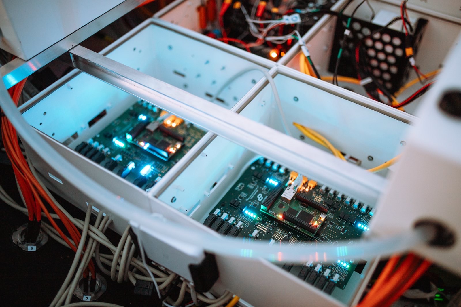
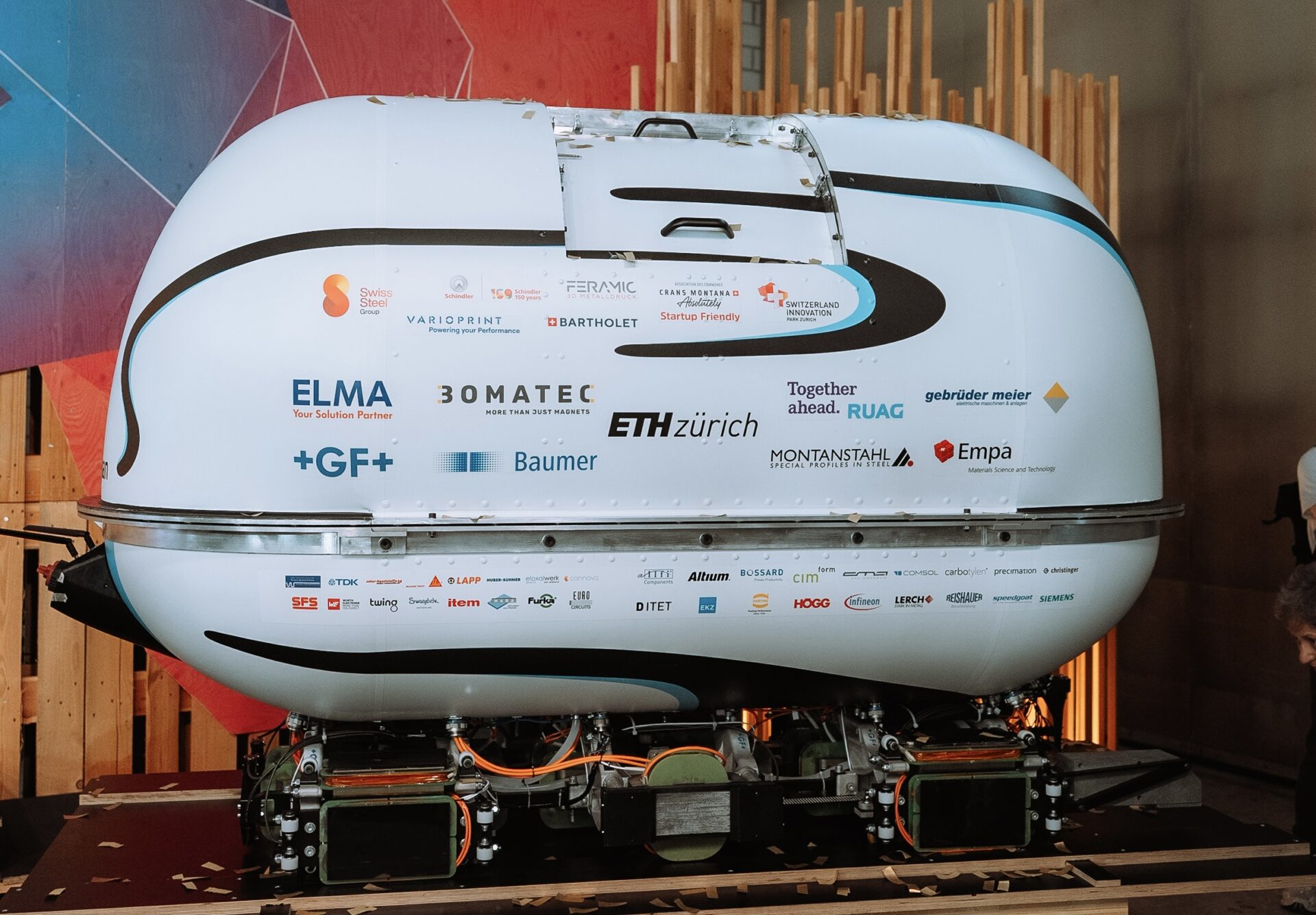
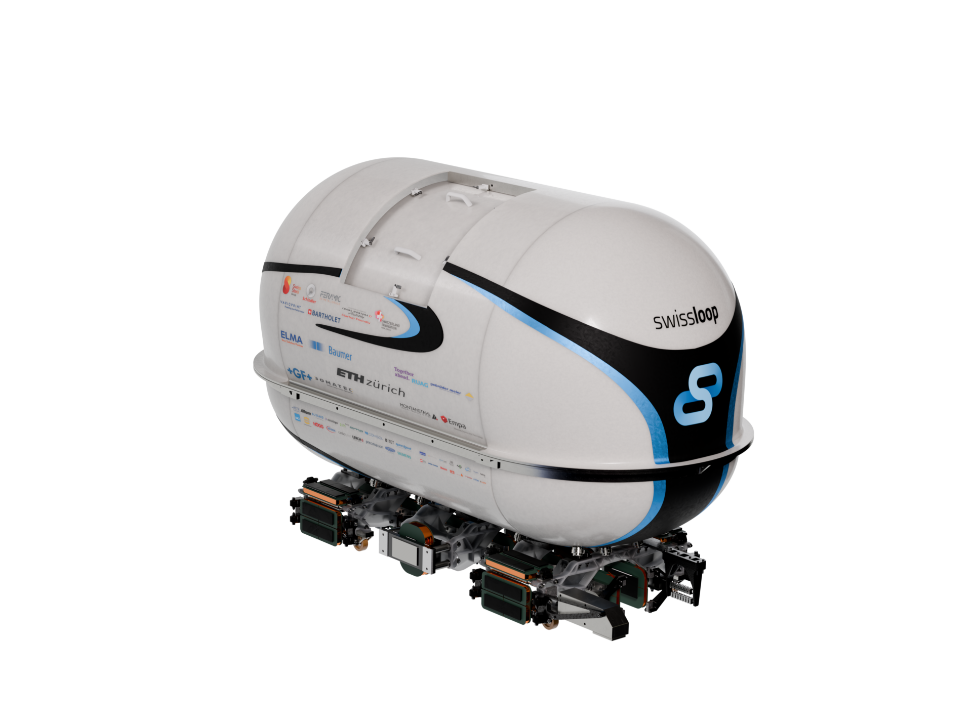
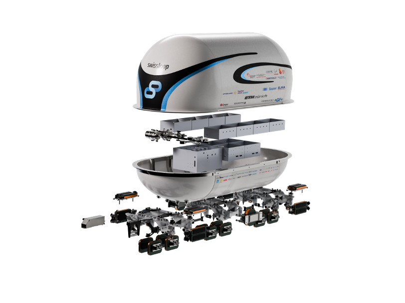
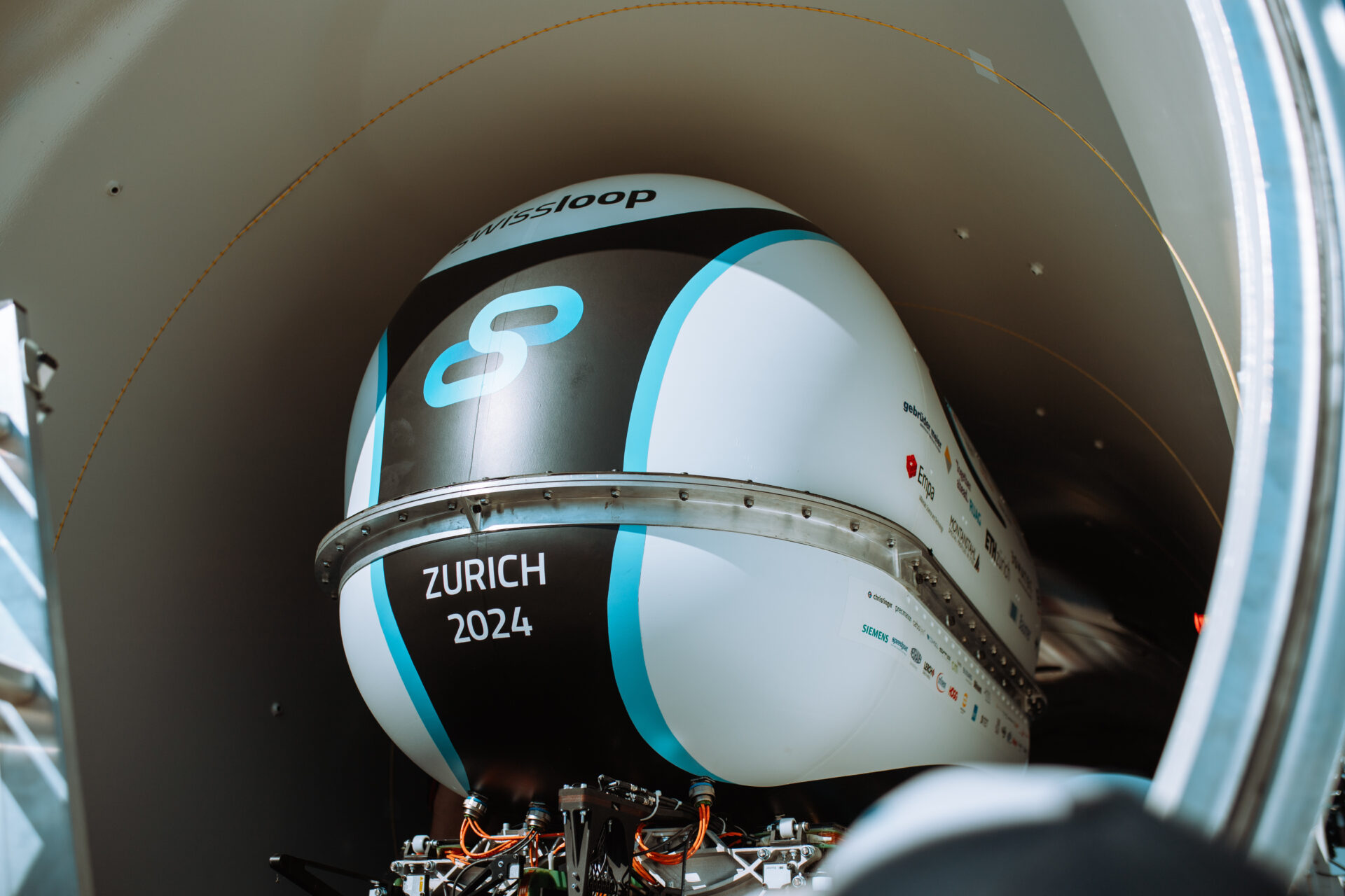
With Sarah Springman Swissloop further pushes the boundaries of hyperloop technology.  Vacuum is one of the key pillars of the Hyperloop concept, hence a major focus of Sarah Springman has been on making the system fully vacuum-compatible. As the first student team in the world, Swissloop developed a hyperloop pod with a completely vacuum-sealed cabin. This cabin not only houses the electronics but also provides enough space for a passenger, including an easy entry and exit system thanks to a fast-closing and opening door.

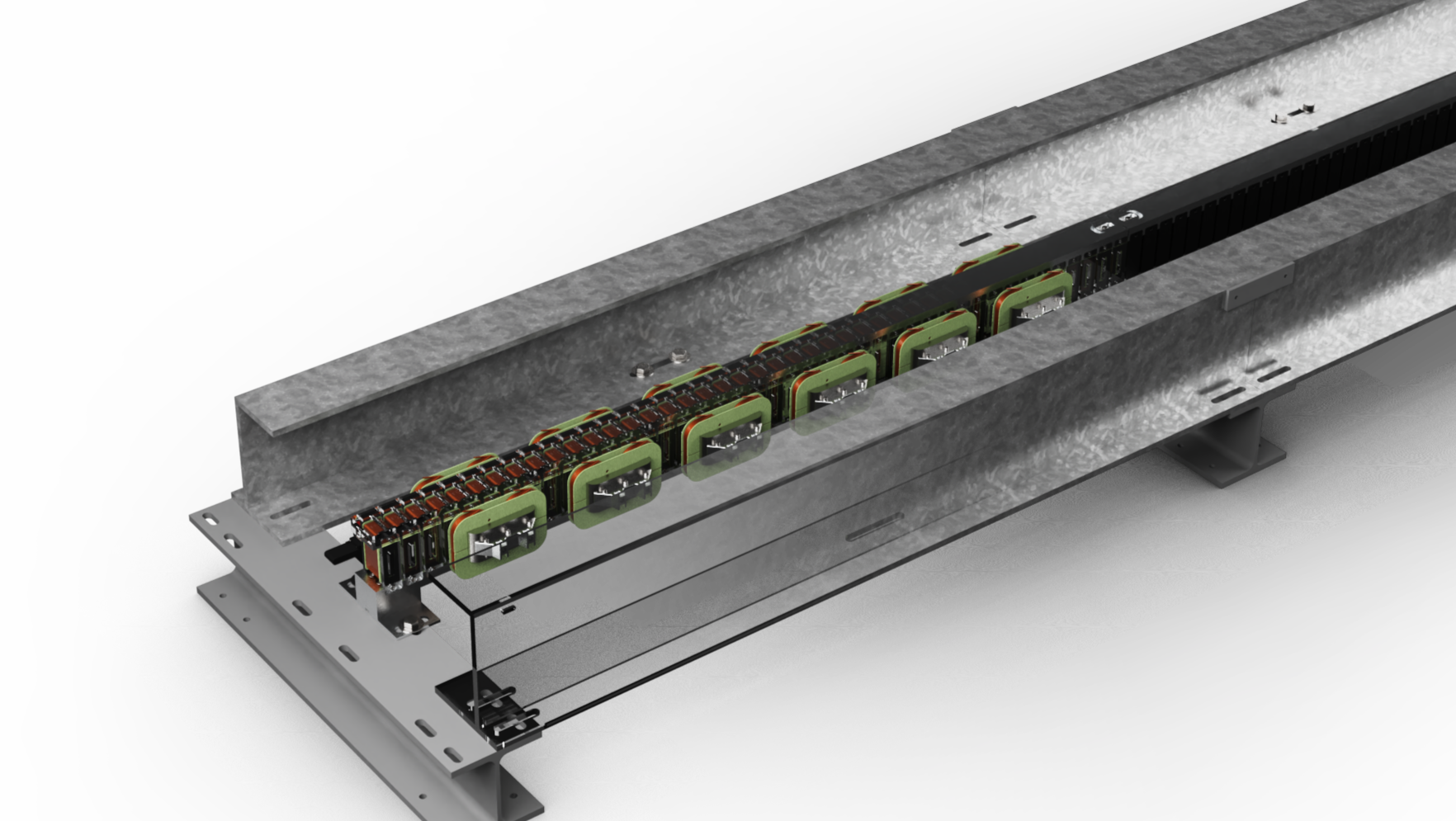
Further the Springman pod not only consists of an active pod but also of an active track called booster. The booster is designed to accelerate the pod to cruising speed. As a result, the newly developed motor of the pod could be optimized for maximum efficiency at cruising speed.

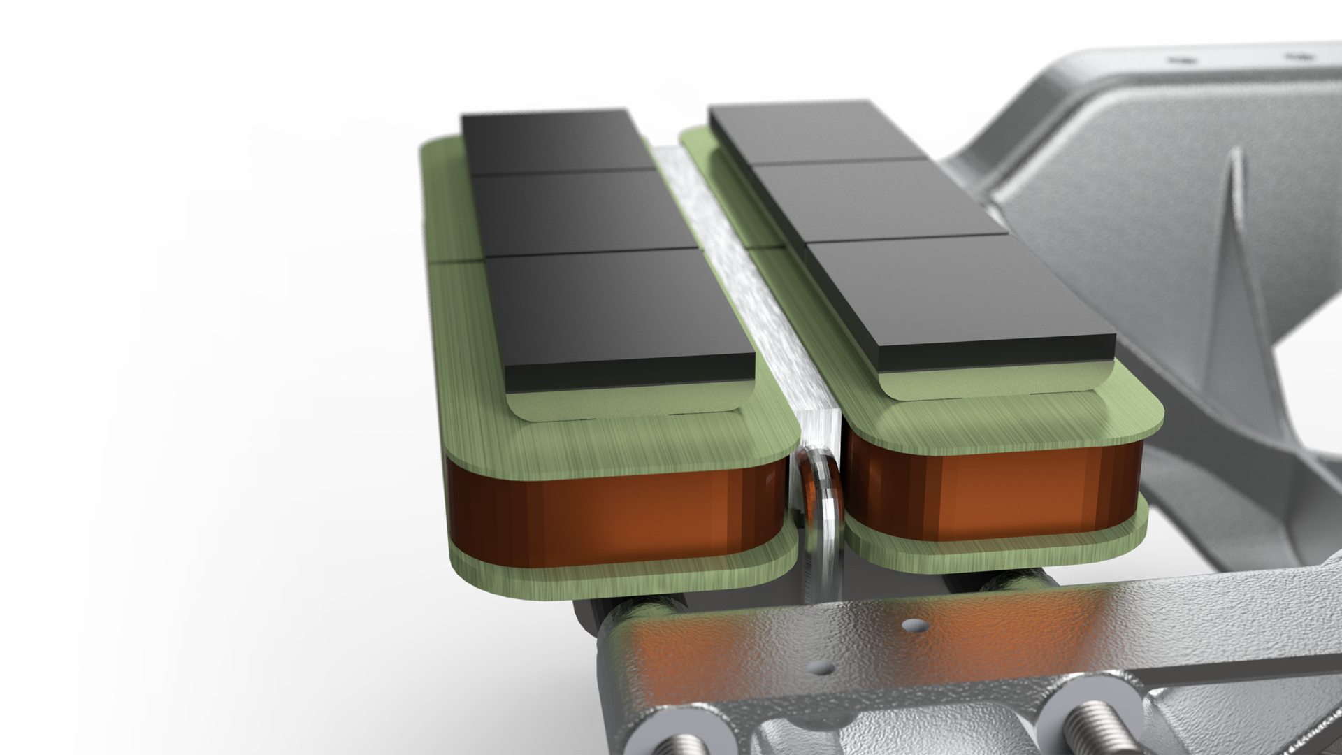
Sarah Springman again incorporates a combination of lateral electromagnetic suspension in combination with a vertical hybrid electromagnetic suspension, enabling incredibly efficient levitation.

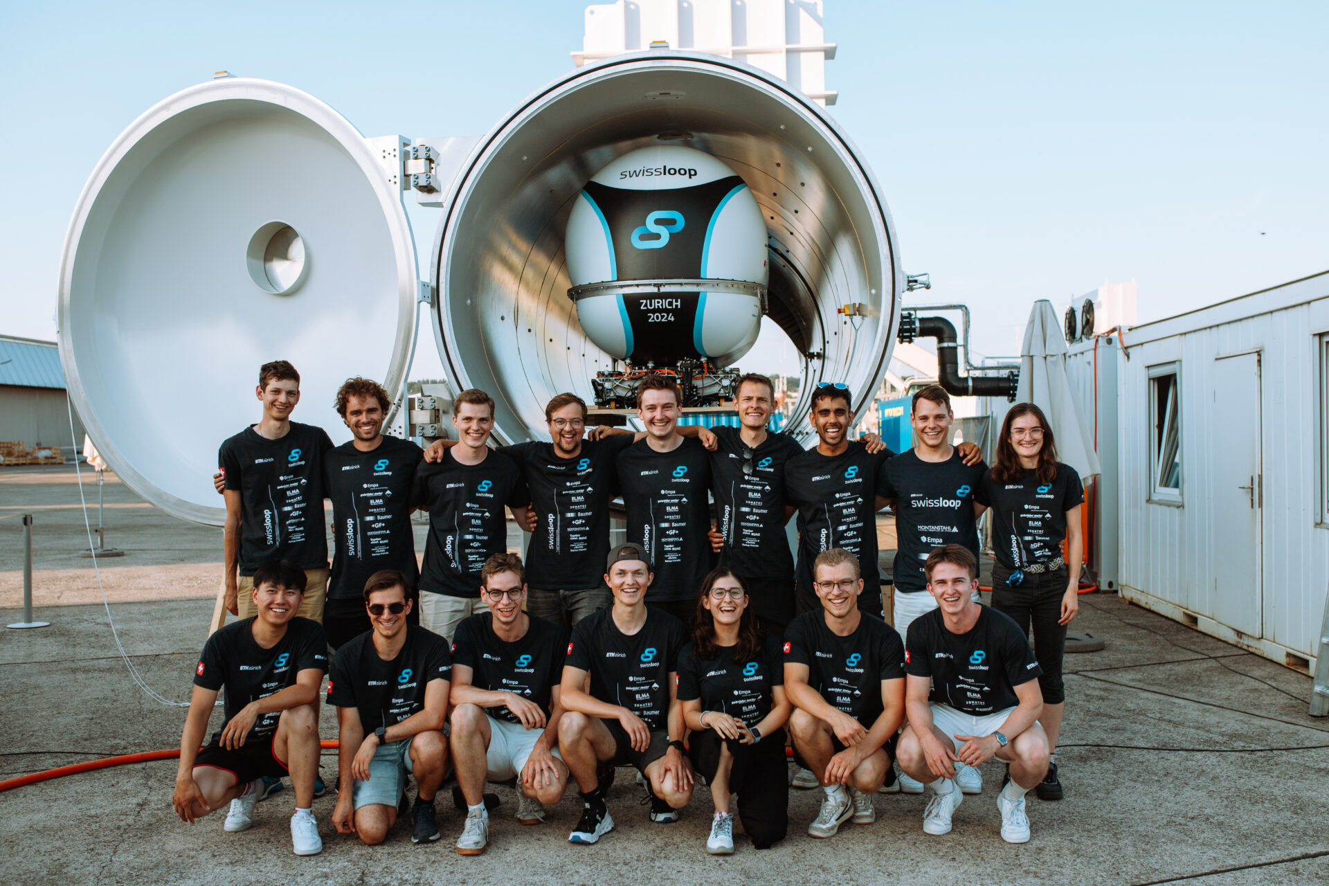
Sarah Springman is the remarkable result of the combined efforts of a team comprising around 38 talented ETH Zurich students hailing from diverse backgrounds. Throughout an intense ten-month season, starting in September, a core group of sixteen exceptional electrical and mechanical engineers dedicated themselves to the design, manufacturing, assembly, and testing of this intricate prototype.

Electromagnetic

The propulsion system includes a booster and a cruising motor. The booster accelerates the pod to cruising speed, reducing on-board battery capacity needs. Upon reaching cruising speed, control transitions to the cruising motor, allowing for a passive track and optimized efficiency at that speed.

The cruising motor aims to reduce power consumption in hyperloop systems by maximizing efficiency during cruising. Accelerated by the booster, the Permanent Magnet Assisted Linear Reluctance Motor (PMALRM) is optimized for a target speed of 45 km/h. Its fully passive stator, made of laminated steel and aluminum, eliminates the need for costly magnets, reducing complexity and cost. This efficient, scalable design enhances the feasibility of hyperloop technology for large-scale projects.

The booster motor, comprising three sections totaling 6 meters, offers modularity for easier installation and scalability. Mounted centrally on the track, it replaces the passive propulsion beam in the booster section. Designed as a three-phase linear synchronous motor using the on-board motor as the complementary part, the booster generates the force to accelerate the pod, while the cruising motor closes the magnetic circuit to enable force generation.

Since last year’s levitation system proved to be highly effective, the “Hybrid Electromagnetic Suspension” (HEMS) levitation method has been used again this season. The insights from the last season were incorporated, and the levitation system was improved with several innovations, making it more efficient.

The braking system consists of redundant electromagnetic power off brakes. They operate similarly to conventional pneumatic brakes, where springs press the brake pads onto the track in the engaged mode. Further, permanent magnets attract themselves to the track and thus provide additional normal force. To disengage the brakes, current is run through the electromagnet, which pulls the brake pad back and disengages the brake. During the disengaged state, only a much smaller current is necessary as the force of the electromagnet increases quadratically with the decreasing airgap between the stator and the mover. The brakes are powered by their own low voltage batteries and a peak current of 18A.

Electrical

The electronics are namely divided into two parts: the high voltage system and the low voltage system.

At the core of the low voltage system are the vehicle control unit and the booster control unit, which are responsible for the overall control of the pod and booster. They collect data from countless sensors and communicate with all other systems and the control station via a self-developed combined CAN and Ethernet network, allowing reliable transmission of messages, data, and commands over the optimal medium.

The universal control unit is the link between the power converters and the low voltage system. This control unit performs all functions necessary to control the motor, booster and levitation.

The universal power converter consists of two H-bridge circuits with SiC MOSFETs. Efficiency  and interoperability between motor, booster and levitation are at the core of its design. The converter is designed for a peak voltage of 1100V and can deliver up to 75A continuously and thereby is the powerhouse of the pod.

The battery completes the high-voltage side of the system. Li-Po batteries were used for high power density. These are connected in 120V modules, which can be combined modularly to achieve a maximum voltage of 720V. The batteries are monitored for temperature and cell voltage to ensure the safety of individual cells, as well as for total voltage and current to ensure that they operate within the expected and safe range.

To increase the safety and reliability of the fail-safe electromagnetic brake an independent electrical system was developed. An asymmetric bridge is used to convert the necessary power. This circuit board also includes battery monitoring for the brake batteries, charge and discharge mechanisms for the brake’s capacitors, as well as voltage and current measurements.

Watch the making of the Sarah Springman pod

Mechanical

As the concept and the design of last year’s track proved to be advantageous, the outer beams and the sleepers are reused from last year. This enables Swissloop to increase the length to 100 meters and thus test the system in an environment that allows for tests more similar to a full-scale Hyperloop system. Thanks to the modular design, which allows changing only one of the beams, the propulsion beam has been modified and upgraded, and is entirely compatible with the previous track design.

The chassis frame is cast from aluminum and was designed with the help of bionic form generation to allow for a maximum strength to weight ratio. This design and manufacturing process is what is used in the automotive industry for prototype cars and is compatible with full-scale mass production. The complete structure consists of three individual frames which are made into a single rigid structure with connection pieces. Its purpose is to provide mounting to all external components of the pod, such as the electromagnets and sensors.

The Pressure Cabin is located on top of the chassis frame and is made from milled aluminum ribs, aluminum sheet acting as the skin and endcaps made from composites. It is isolated from the outside to increase the pressure up to 0.8 bar with respect to the outside pressure. The electronics, the pressure regulation system and the cooling system are stored in the lower cabin. The upper cabin provides space for one passenger. Additionally, the pressure cabin features a carbon-fiber reinforced chair designed for one passenger.

Safety has always been a priority for us. To further ensure the safety of the electronics and, more importantly, future passengers, we developed a pressure regulation system that can maintain a pod pressure of 0.8 bars even if leakages should occur.

In addition, compared to the previous year the vacuum-compatible phase-change cooling system was expanded, so that, along with the power electronics, the levitation system is now also actively cooled.

426

Weight

1.14

Acceleration

30

In Vacuum Environment

3

Awards @ EHW

Sarah Springman

Dame Sarah Springman is a British-Swiss triathlete, civil engineer, and academic. and former rector of ETH Zurich. She served as an inspiring and visionary namesake who has long been an advocate for women in STEM and academia.